C-5A Galaxy Stability Control Analysis
For one of my senior projects, my team and I designed and implemented an autopilot control system for the Lockheed C-5A Galaxy as shown in figure 1. We focused on analyzing its stability, creating a mathematical model, and designing a PID controller to stabilize pitch, yaw, and heading angles. Using MATLAB and Simulink, we simulated the aircraft's longitudinal and lateral stability, then applied control theory to improve the aircraft’s dynamic response.
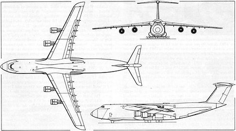
Figure 1. A Lockheed C-5A Galaxy.

Figure 2. Response graphs for the longitudinal directions.
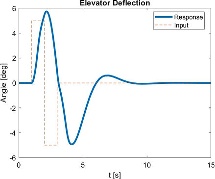
Figure 3. The PID response of the elevator deflection for yaw control.
Our initial analysis of the longitudinal dynamics for the C-5A Galaxy revealed inherent instability in the open-loop system, as evidenced by open-loop poles with a positive real component. As shown in figure 2, examination of key variables showed that forward velocity (u) was statically stable and dynamically neutral, with a stable initial response and consistent oscillation amplitude. The angle of attack (α) and pitch rate (q) both demonstrated static and dynamic stability due to gradually diminishing oscillations. However, the pitch angle (θ), while statically stable, was dynamically neutral, as oscillation amplitude remained constant but was small enough to suggest an overall stable response.
After implementing the PID controller for longitudinal stability, the C-5A Galaxy demonstrated both static and dynamic stability in pitch control. The system now reliably stabilizes at desired pitch values, with responses that converge as expected. While the controller ensures stability, it does introduce a slight delay in reaching ideal deflection times for the elevator. Specifically, the elevator deflection achieves the desired angle in 2 seconds instead of the ideal 1 second, and the maximum deflection reaches 6 degrees instead of the target 5 degrees. However, oscillations are minimal, and stability is quickly achieved by 8 seconds after initialization, as shown in figure 3. The controller’s maximum elevator deflection requirement of ±6° remains well within the C-5A’s operational limits, which span from -25° to +15° for elevator deflection. This margin confirms that the controller design is both effective and safe for implementation, allowing adequate room for operational tolerances.
In the lateral direction, the initial open-loop analysis revealed inherent instability in the C-5A Galaxy’s lateral dynamics. The pole locations varied, with some poles showing positive real parts, indicating potential instability, while others were negative or close to the origin, making the system highly susceptible to disturbances like turbulence. To further assess stability, the roll rate (p), yaw rate (r), side-slip angle (β), heading angle (Ψ), and roll angle (ɸ) were evaluated individually. As shown in figure 4, these variables exhibited static stability with an initial response toward the neutral axis, but were dynamically unstable as they diverged from the neutral axis over time. This divergence confirmed the need for a closed-loop control solution to ensure lateral stability and reliable roll performance in variable conditions.

Figure 4. Stability graphs for the latitude direction.
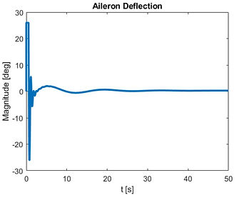
After implementing the PID controller for roll stability, the C-5A Galaxy achieved both static and dynamic stability in the lateral direction. The system’s initial response stabilizes at the neutral axis, confirming static stability, while long-term responses from the roll angle, aileron deflection, and command heading angle converge to the desired values, as shown in figures 5, 6, and 7. As seen in figure 5 the roll angle stabilizes within approximately 10 seconds, a reasonable result given the complexity of the dynamics. Once the desired roll angle of 5 degrees is reached, oscillations are minimal and nearly unnoticeable. Figure 6 shows that the command heading angle achieves stability within about 15 seconds, with no oscillations, meeting stability requirements. Figure 7 demonstrates that the aileron deflection reaches stability in about 5 seconds, with oscillations that gradually decrease over time. However, the aileron deflection required for stabilization is ±25°, which matches the aircraft’s deflection limits as specified by Lockheed. While this deflection is achievable, it leaves no margin for error, making the controller effective but not fully practical for operational safety in highly variable conditions. This assessment demonstrates precise capabilities in control design and dynamic stability analysis to achieve stability while highlighting potential constraints on safety margins.
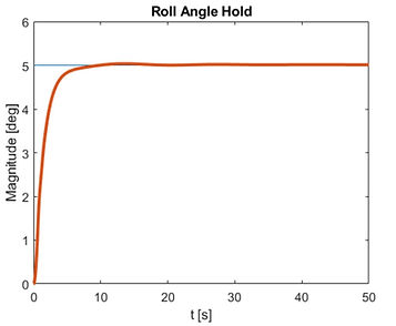
Figure 5. Time required for the roll angle to reach desired value
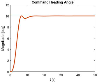
Figure 6. Time required for the heading angle to reach the desired value